
- Building a Cellular Man-in-the-Middle Setup for 4G - 24. January 2023
With the ongoing rise of the Internet of Things (IoT) and current 4G/5G technologies, testing connected devices and mobile communcation in terms of security is more important than ever before. Approriate testing enviromnents are required in order to examine devices that transmit data over cellular networks.
With this 4G test setup, it is possible to redirect the internet traffic, normally sent over the mobile network, through a dedicated test network. This enables testers to intercept, redirect and modify the traffic with tools like mitmproxy or mitm_relay.
In this article, a suitable way to build a MitM setup for 4G devices will be described. Furthermore, some test cases as well as technical limitations will be covered.
At the time of writing this article, no open source software that could be used to set up a fully functional 5G testing network is available. However, there are some 4G software suites which implement more and more 5G features over time. So this article focuses mainly on 4G only, but there is a chance that the shown software suite will eventually support 5G, too.
The Requirements
In order to build a 4G test setup, the following operating system, soft- and hardware tools are required:
Operating System
- Ubuntu – 16.04 LTS, 18.04 LTS or 20.04 LTS
- Arch Linux
- openSuse
- other Debian-based distributions
Software
- Wireshark network analyzer
- mitmproxy intercepting proxy
- mitm_relay intercepting relay
- pysim for programming SIM cards
Hardware
- RF-shielding box (VERY IMPORTANT TO COMPLY WITH LEGAL REGULATIONS!)
- Software-Defined Radio (SDR)
- Ettus B200 or B210
- BladeRF (using the BladeRF 2.0 Micro xA4)
- LimeSDR
- 2 Antenna cables
- two antennas
- programmable SIM cards (using the sysmoISIM-SJA2 from Sysmocom)
- a smart card writer
- SIM breakout board
The Basics
The 4G Infrastructure
This is only a rough overview of the LTE infrastructure. A more detailed explanation can be found here and here.

User Equipment – UE
The UE is the device which connects to the mobile network. In most cases, it is a mobile device, like a smart phone, but it could also be an IoT device as well. Inside the UE, there is a Universal Integrated Circuit Card, in short UICC, also known as (U)SIM. This smartcard enables the UE to establish a connection to the LTE network and is essential for successful communication.
Evolved universal Terrestrial radio access network – e-utran
The E-UTRAN is mainly responsible for the radio communication. It only has one element, the evolved Node Base Station, or eNB in short.
The Evolved Packet Core – EPC
The EPC is the core network and heart of the LTE technology. Within the EPC, the UEs are authenticated, the communication will be established and the data traffic is redirected to other multimedia networks, like the Internet. The EPC consists of many different elements:
- MME – Mobility Management Entity: ensures that the connection to the network is kept alive when changing from one radio cell to another
- HSS – Home Subscriber Server: database with all IMSIs and their keys, which are required to identify SIM cards and establish encrypted connections
- P-GW – Packet Data Network Gateway: connects the EPC to networks such as the Internet
The SIM Card and its Identity
The IMSI is a unique identification number that every SIM card has. It identifies the UE within the LTE network and has a maximum length of 15 digits. The first few digits of every IMSI represent the MCC and the MNC. The MCC is the Mobile Country Code and identifies the country, the mobile network operator resides in. The MNC (Mobile Network Code) identifies the mobile network operator. For example, the German mobile network operator Telekom has the following MCC and MNC: 262 01, where 262 means Germany and 01 means Telekom. A list of all global MCCs and MNCs can be found here.
The Test Setup
The core of the test setup is the srsRAN suite from Software Radio Systems.
Featuring both UE and eNodeB/gNodeB applications, srsRAN can be used with third-party core network solutions to build complete end-to-end mobile wireless networks. For more information, see www.srsran.com.
Currently, the srsRAN suite includes the following parts:
- srsUE
- a full-stack 4G UE application
- it also implements a 5G Standalone and Non-Standalone UE
- not needed in this setup
- srsENB
- a full stack 4G eNodeB
- it also implements 5G Standalone and Non-Standalone gNodeB capabilities
- srsEPC
- a light-weight 4G EPC implementation with MME, HSS and S-/P-GW
The srsRAN suite can be installed either from source or by using the third-party repository provided by Software Radio Systems. This depends on the used operating system as well as the used SDR hardware.
For more information and detailed installation instructions, please check out the official documentation.
After srsRAN is successfully installed, everything is ready to go. Please note that the other resources mentioned above are considered as already installed.
Running The 4G Network
Warning: Before executing any of the following commands, please note that the used frequencies for mobile communication are licensed. In other words, it is illegal to transmit on these frequencies without proper permission! And trust me, you don’t have that…
In order to stay on the right side of the law, all of the upcoming actions have to be performed with the SDR inside an RF-shielding box.

Configure the Network
srsRAN comes with some default configuration files. We will take a closer look at them in a minute, but for now we have all we need. As a test client, we use a standard smartphone with a swappable SIM card. The phone must be put inside the RF-shielding box.
First, we run the srsEPC from the terminal. This is the 4G core network with components like the MME, the HSS and the gateways P-GW and S-GW. You can learn more about the basic 4G architecture here.
$ sudo srsepc
After the srsEPC started successfully, we launch the srsENB, the 4G base station, which is responsible for radio communication, in another terminal.
$ sudo srsenb
If srsEPC and srsENB are both running successfully, the mobile network is available inside the shielding box. Whether or not the mobile device tries to connect to the test network depends on the used SIM card. The default configuration of srsENB and srsEPC sets the MCC to 001 and the MNC to 01, which are the IDs for a test network. However, within the two configuration files enb.conf and epc.conf, the values can be changed to mcc=262 and mnc=01,which are the IDs for a German Telekom network.
If the UE recognizes the mobile network, it will try to connect to it. This can be seen in the output of the terminals where srsEPC and srsENB are running. However the attach request will fail because of an “User not found in HSS” error. This behavior is expected. Unlike the 2G standard, 4G requires mutual authentication, meaning that the UE and the EPC must authenticate each other. Because of this, a malicious base station cannot easily be used in 4G, as it was possible in 2G.
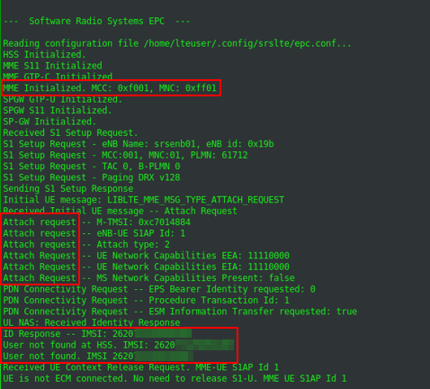
The attach request is rejected by the EPC, because of an unknown IMSI.
Programming the SIM Cards
In order to get a valid communication between the UE and the 4G test network, the SIM card must be known to the 4G network. This means, the HSS must have an entry of the SIM cards IMSI, together with different keys for the traffic encryption. The bad news are, it is nearly impossible to get these values from an ordinary SIM card, for security reasons.
The good news are, it is not essential for this setup, because of the programmable SIM cards. I recommend the sysmoISIM-SJA2 cards from Sysmocom. I also tried some so called Green Cards from China, but without any success.
When ordering the sysmoISIM-SJA2 cards, you’ll also get a file with all the values you need. This includes, among other, the IMSIs and the private keys. There is also the ADM PIN, which is required to program the SIM card, the ICCID, another id of the SIM card and the OPc value. The OPc value is an already encrypted value, used as key for transport encryption.
At this point it would be enough to just enter the values, Sysmocom delivered into the user_db.csv file, as shown below:
# name,
# auth algorithm (xor|mil)
# imsi
# key
# opc tpe (op|opc)
# op/opc
# amf
# sqn
# qci
# ip address, either a static IP or the value dynamic to get the IP from DHCP
ue1,xor,001010123456789,00112233445566778899aabbccddeeff,opc,63bfa50ee6523365ff14c1f45f88737d,9001,000000001234,7,dynamic
In some scenarios, the UE is not a smart phone but an IoT device. It might be possible that the device uses a specific SIM card and checks the used IMSI. In this case, it is necessary to program the SIM card to the specific IMSI. This can be done with the suite pysim.
Let’s assume the IMSI must be set to the value 26201987654321. The card can be reprogrammed like this:
$ ./pySim-prog.py -p 0 -t sysmoUSIM-SJS2 -a 58001006 -x 262 -y 01 -i 26201987654321 -s <ICCID> -o 63bfa50ee6523365ff14c1f45f88737d -k 00112233445566778899aabbccddeeff
Please note, if programming the SIM without the -o and -k values, pysim set random values for them. You may want to keep track of the current key and OPc values of you SIM card in order to avoid future problems ;-).
Now the self programmed SIM card must be inserted into the UE.
It is also possible to change the MCC and MNC of the LTE network. Through this, the setup mocks a real mobile network. As mentioned above, the combination 262 01 represents the German telecommunication provider Telekom. In order to change the configuration of the testsetup, the two configuration files enb.conf and epc.conf must be edited. Please note, when changing the MCC and MNC, both configurations need to be identical. A MNC=262 inside the enb.conf and a MNC =001 inside the epc.conf won’t work.
Reaching the Internet
After the IMSI and the corresponding keys are set within the HSS of the test network, the UE is able to start a successful attach request and build up a connection to the 4G test network.
At this point the UE is still not able to connect to the Internet over the mobile network. In order to achieve this, two configurations are required. First, IP masquerading must be set on the notebook, where the 4G test setup is running on. The easiest way to do this, is by using the script srsepc_if_masq. See here for more information.
Second, an access point must be set within UE. The procedure is highly depends on the UE you are working with. On an Android/iOS smart phone this setting can be found in the network settings. Other devices might be configurable via AT commands or a proprietary interface. An example for Android is shown below. An IoT device has it’s pre-configured APN, which might not be changeable. The name of the devices APN can be found inside the /tmp/epc.pcap file.
In this case, the APN of the test network can be set in the epc.conf file: apn = myapn.
Getting a Connection with(out) eSIM’s
When it comes to IoT devices connecting to their corporate back-end over 4G, it is often the case, they use an electronic SIM card, or eSIM in short.
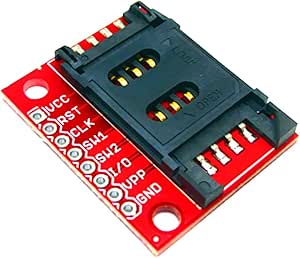
If that’s the case, the eSIM must be de-soldered and replaced by a SIM breakout board, so the self programmed SIM card can be used.
The eSIM pinout is standardized in the TSI 102 221 and is therefor “easy” to de-solder as soon as it’s located. An eSIM has 8 pins, but only 5 of them are of interest.
| Description Left | Pin Left | Pin Right | Description Right |
|---|---|---|---|
| GND | 1 | 8 | VCC |
| No Connection | 2 | 7 | RESET |
| I/O | 3 | 6 | CLK |
| No Connection | 4 | 5 | No Connection |
The SIM breakout board has also 8 pins and again, the following 5 pins are required and needs to be soldered on the PCB, the eSIM was soldered:
| Pin Breakout Board | Pin PCB |
|---|---|
| VCC | 8 – VCC |
| RST | 7 – RESET |
| CLK | 6 – CLK |
| I/O | 3 – I/O |
| GND | 1 – GND |
Once the breakout board is soldered on the IoT devices PCB, the self programmed SIM card can be used.
Accessing Data
Once the enb and the epc are running, the network interface srs_spgw_sgi is created. Now it is possible to listen to this interface with tools like Wireshark to eavesdrop the data traffic the UE is sending and receiving.
With the tool mitm_relay it is also possible to relay the traffic over a local web server and intercept it with proxies like ZAP, Burp or mitmproxy.
As long as there is no end to end encryption, the eavesdropped data is in plain text.
Limitations
There are some limitations to this setup, which should also be mentioned here.
We don’t hack LTE, we use it
One of the major misconception about this setup might be its purpose. Hacking a 4G LTE device or even an infrastructure, would mean to exploit existing vulnerabilities or misconfigurations of the LTE infrastructure, its network stack or basic functionalities. There are known attacks against the LTE technology, but non of them come to action in this setup.
This setup is only to gain access to the data transferred from the UE to the back-end and vice versa. A possible scenario could be an IoT device, communicating with a back-end API by using LTE. With this setup, it is possible to actually intercept and even modify the data, as long as it is not end to end encrypted.
There are different types of LTE
This setup only applies to 4G, meaning LTE Advanced, also known as LTE-A or LTE+. There are some derivations of LTE, to better suit the requirements for an IoT infrastructure. Those are Narrowband IoT, Nb-IoT and LTE for Machines, LTE-M. Those two technologies are not compatible with this setup, because of their variational use of the LTE stack.
The SIM card is essential
Back in the days of 2G. It was possible to setup a rouge 2G basestation, and get a working connection with the victims UE just by sending the right signals at the right time. The reason this works so easily was the fact that the 2G basestation does not need to authenticate itself to the UE. With the development of 3G, this behavior changed. Since then, both communication partners need to authenticate to each other.
This makes it impossible to simply build up a rouge basestation, or stingray and intercept the mobile traffic if the victim.